The Big Muff π Page
The Definitive Big Muff Resource and History
VISIT MY SWORDS, KNIVES and FANTASY ART WEBSITE www.kitrae.net
©Kit Rae. Last update July 2012.

Here is a simple primer about the workings inside the Big Muff Pi circuit. The BMP circuit is based on a common amplifier design with clipping diode/feedback loops. Clipping stages in amplifier circuits were nothing new to the effect pedal world when the Big Muff was created around 1969/1970, but what makes the Big Muff circuit unique are two nearly identical clipping sections in a row, one clipping an already distorted signal, and subtle changes in capacitor and resistor values to smooth out and tame that signal as it goes through the mayhem of those two stages.
The typical BMP circuit is made up of 46 components: 4 transistors, 22 resistors, 13 capacitors, 4 diodes, and 3 potentiometers. The circuit is built in five stages: an input/gain stage, first clipping stage, second clipping stage, a tone stage, and output stage. The input stage is a simple amplifier that sets the gain for the circuit and filters some highs and lows. The first clipping stage softly clips the waveform in a feedback loop, creates the distortion, and filters and compresses the signal. The distortion is still rather weak, so a second clipping stage repeats and refines the distorted signal even more, creating what EHX calls the "violin like sustain" Big Muffs are known for. These two cascading soft clipping stages combine to create a hard clip, and function similarly to how cascading drive stages in tube amplifiers work. In the tone section the signal splits apart into a high pass and a low pass filter, which are each then blended back together with the tone potentiometer. One end of the pot rotation is mostly low pass signal and the other end is mostly high pass. There is some bandwidth and gain lost in the tone section signal blend, which creates the trademark mid range notch, or "scoop" the Big Muff is so well known for. The output stage then recovers the gain lost in the tone stage.
 ...
...  ...
...
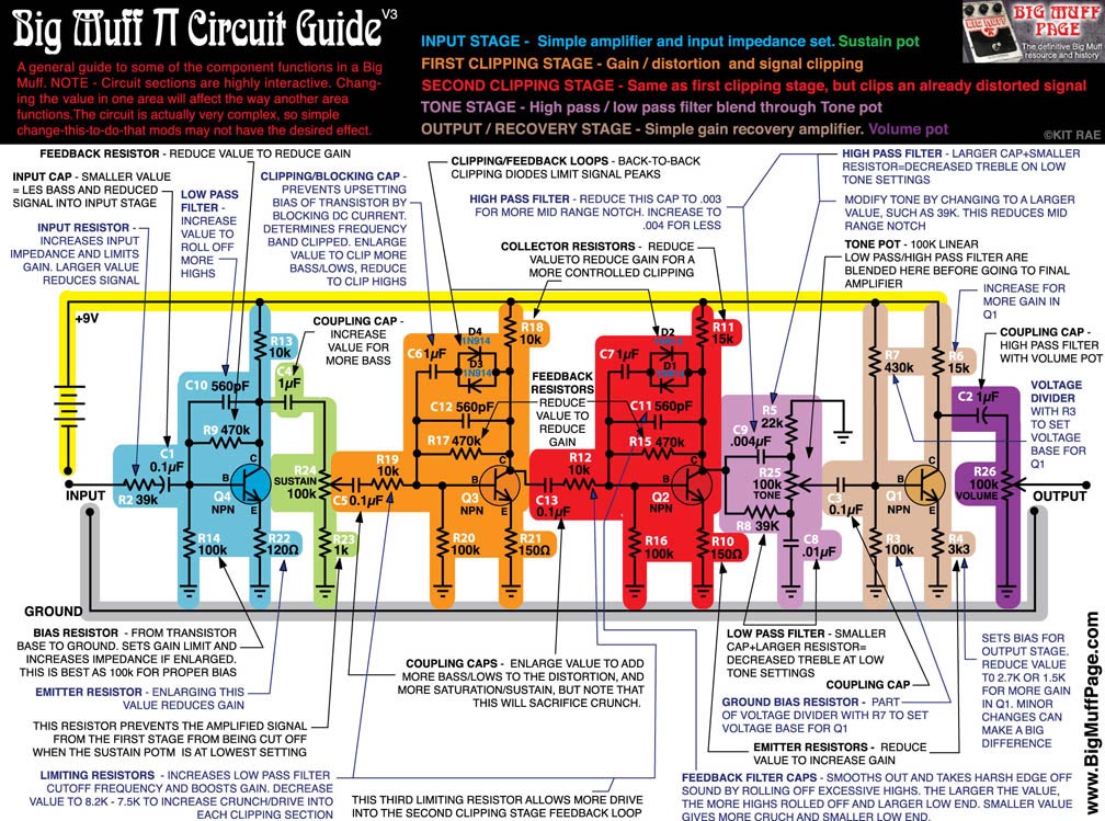
CIRCUIT GUIDE - Without getting into too much detail, below is a simple Big Muff Circuit Guide using a typical version 1 and version 2 Big Muff PCB trace, with stages broken out by color, and a schematic with explanations of some of the individual section functions. The colors shown on the circuit photos match the corresponding colored sections on the Circuit Guide schematic. Keep in mind that my notes about how the individual components affect the circuit are a rather simplistic guide. Changing a value in one stage affects the circuit in other areas. There is a give and take each time something is changed, a very complex interaction, so experimentation is key to altering or creating a Big Muff circuit to get the most desirable sound. Using this may help with an undertsanding of why one particular vintage or modern Big Muff may sound better/worse/different than another, or in creating or modifying your own circuit. The Big Muff is a very forgiving circuit, and there are multiple ways of achieving different sounds.
WHY ARE THE TRANSISTORS LABELED IN THE REVERSE ORDER? - Note that Q1-Q4 are labeled in reverse order from input to output on the schematics. This is due to the fact that both V1, V2, and V3 Big Muffs have them printed in this order on the PCB's. To keep it from being confusing for those reading thier PCB's, and to keep the tradition, we have used this order on all Big Muff schematics.
CLICK ON AN IMAGE TO ENLARGE
KEY TONE COMPONENTS - If you study the various vintage Big Muff Pi circuits and schematics on this website you will find a very wide variety of components values used from circuit to circuit, even among circuits in the same enclosure. Spread across thirty-five caps and resistors, it may seem mind boggling to keep up with how each of these these may affect the sound, but looking at the circuit architecture, only a few of these have a major impact on the tone. The rest can have values that vary slightly and not influence the tone in any great way. The ones I have found that make the most difference in sculpting out unique tone differences are the Feedback/Filter Caps, Clipping/Blocking Caps, and the Tone Stack Filters. These really define what makess one version different from another more than anything else.
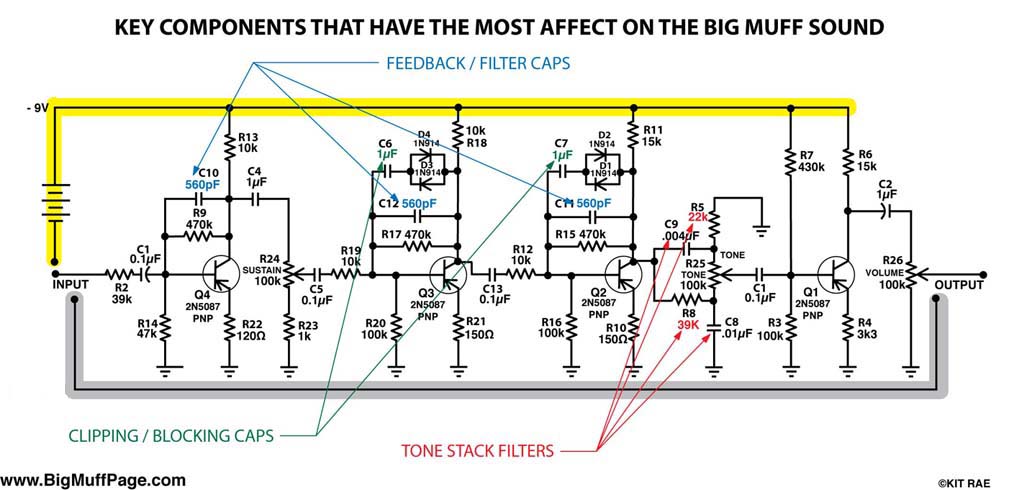
Clipping / Blocking Caps - These two caps determine the bandwidth to be clipped by the diodes in the two Clipping Stages, and have the most affect on the sound of the Big Muff. Typically they are identical in each stage, though I have seen many examples of V1 and V2 Muffs where the cap in the first stage was smaller than the second. When both caps are identical, smaller values remove more high frequencies, increasing bass, and larger values remove more low frequencies, decreasing bass. This has the effect of determining if a Big Muff will sound huge boomy/bassy, or less bassy/chunky. When the cap in one clipping stage is different from the other, the difference is not as great as when both are changed. A BMP with .12uF in the first and 1.0uF in the second will sound in between one with two .12uF caps, or two 1.0uF caps.
•V1 Triangle Big Muff - Clipping cap values ranged from .05uF, .1uF, .12uF, and 1.0uF, giving a wide variety of bass response from unit to unit. You will find the same range on the Guild Foxey Lady version.
•V2 Ram's Head Big Muff - Clipping cap values ranged from .047uF, .1uF, .12uF, and 1.0uF clipping caps. That is one reason why there is not really a definable difference in a Ram's Head Big Muff and a Triangle, other than the enclosure. They both spanned the same wide range of possible sounds. You will find the same range on the Guild Foxey Lady version of the V2.
•V3 and V6 Big Muffs - Clipping cap values were almost always 1.0uF.
•Russian Big Muffs - Clipping cap values were almost always .047uF, which is why they sound so smooth and bassy/boomy.
•V9 Big Muff Reissue - Clipping cap values were alwasy 1.0uF.
•V10 Little Big Muff - The modern Little Big Muff uses .1uF caps.
Feedback / Filter Caps - These three caps usually have identical values to each other in any given Big Muff circuit. They are responsible for how fizzy/buzzy a Big Muff will sound. Essentially they filter the amount of high frequencies in the bandwidth, determining if a Muff will sound more on the smooth side or the harsh side. In conjunction with the Clipping Caps, they can make the bottom end sound hollow and bassy, or thick and chunky. Larger values roll off more highs and smaller values give more crunch and buzz to the sound. The better sounding vintage Big Muffs tend to have the larger values and sound smoother and warmer. Modern Big Muffs tend to have the lower values and sound a bit more buzzy/fuzzy.
•V1 Triangle Big Muff - Feedback cap values were almost always 500pF, but there was one schematic variant that used 560pF caps, and a very small number were made with 470pF. You will find the same range on the Guild Foxey Lady version.
•V2 Ram's Head Big Muff - Feedback cap values started with 470pF, then jumped up to 680pF with a 220pF in the input stage for one version, then alternated back and forth between 470pF and 560pF. There are a few rare instances where 500pF was used. This is one area where the V1 and V2 Big Muffs were usually different. You will find the same range on the Guild Foxey Lady version.
•V3 and V6 Big Muffs - V3 feedback cap values were almost always 470pF, but one early variant used 560pF. The V6 aways used 470pF.
•Russian Big Muffs - Feedback cap values ranged from 430pF on early models, to 500pF(the Civil War model) to 470pF on later green and black versions.
•V9 Big Muff Reissue and V10 Little Big Muff - Feedback values were always 470pF.
Tone Stack Filters - Big Muffs are known for their trademark mids scooped tones, meaning the mid frequencies are removed from the bandwidth, making the sound very deep and dark. Some Big Muffs are more mids scooped than others, and the frequency of the scoop may be higher or lower in the bandwidth. The less scooped, the brighter the Muff sounds and more easily it will stand out in a band mix with the bass guitar and other instruments that may occupy the same frequencies. The more mids scooped, the deeper and darker the tone sounds. Two filter resistors in the tone stage determine the amount of mids that are scooped, or removed. The high pass resistor (22k in the example above) determines the midrange notch. Higher values have less mids scooped out and lower values have more mids scooped. This resistor also works in conjunction with the high pass tone capacitor (.0004uF in the example above) to affect the treble at low tone settings. Reducing this cap to .003uF alters the range and scoops slightly more mids. Increasing to .004uF reduces the scoop. Combined, a larger high pass cap and smaller resistor decreases the treble at low tone settings. The low pass resistor (39k in the example above) works in conjunction with the low pass filter cap (.01uF in the example above) to also affect the treble at low settings. A smaller cap and larger resistor will also reduce the treble at low tone settings.
•IV1 Triangle Big Muff - The high pass resistor value was 27k in the early units, but 33k was the most common. 22k and 39k were also used, but rarely. You will find the same range on the Guild Foxey Lady version.
•V2 Rams Head Big Muff - The high pass resistor value started with 33k, which was the most common value. 22k was the second most used, but there were also some variants that used 39k.
•V3 Big Muff - The high pass resistor value was most commonly 22k, but 39k were also used.
•V6 Big Muff - The high pass resistor value was 39k.
•Russian Big Muffs - The high pass resistor value was almost always 22k high pass resistors, creating heavy but smooth bass with the mids scoop frequency boosted a bit.
•V9 Big Muff Reissue - The high pass resistor value was 22k, then later 27k.
•V10 Little Big Muf and V11 Bass Big Muff - The high pass resistor value was 22k.
•V1 Triangle Big Muff - The low pass resistor values started with 27k. 33k was the most used. Other variants used 22k and 39k.
•V2 Rams Head Big Muffs - The low pass resistor values ranged equally from 33k to 39k.
•V6 Big Muff - The low pass resistor value was 39k.
•Russian Big Muffs - The low pass resistor values were alwasy 20k, changing to a 22k for the last black boxed Russian version.
•V9 Big Muff Reissue - The low pass resistor values were 22k, 39k, and later 27k.
•V10 Little Big Muff - The low pass resistor value was 22k
•V11 Bass Big Muff - The low pass resistor value was 11.5k.
OTHER DISCUSSIONS OF THE CIRCUIT - Below are a few other good discussions of the circuit. Feel free to pass along any others you may come across if you think they would be of interest, or let me know of dead links. My email addy is on the home page.
The Large Beaver - A Walkthrough - Very good explanation of every stage of the Big Muff, in the form of the BYOC Large Beaver. I highly recommend anyone interested in building a vintage Muff clone start with this kit, and if you want to see what changes in component values do first hand, socket everything so you can trade out components on the fly.
Technology of the Big Muff - What Does What? - Thanks to RP for alerting me to this thread on the DIY forum. A thread started by John Lyons with lots of good details and discussion of the circuit.
Big Muff Pi Mods and Tweaks - A selection of some of the more popular mods.
Determining the Gain Factor of a Big Muff - A good article from the Big Muff Schematics, Articles, and Modifications website.
Calculate the Gain of the Big Muff Stages - Another good thread from DIY about BMP gain
THANKS - Thanks go to Robert P., Jansen, and Matt for assistance. Thanks to Jack Orman for his writings explaining the BMP circuit in his excellent Big Muff and Rat eBook, which got me started many years ago. That took me from barely knowing how or why any components in a circuit do what they do, to still barely knowing, but having a grasp on what they are affecting in this circuit. I also learned a lot from the old ampage.org forum discussions.
Schematics of vintage Big Muffs in my collection, including the most common vintage Electro-Harmonix circuit variants for all versions. Also included are several clones of the Big Muff circuit with unique component values or interesting modifications.
COMPONENT VALUES MAKE THE SOUND - There is a myth that the transistor type is responsible for the sound of a Big Muff being good or bad. Good and bad are subjective terms that will be different for different people depending on their musical or playing preferences, but is actually the mix of different values of all of the components in the circuit (capacitors, resistors, diodes), and how the transistors are biased from the surrounding component values that make one Big Muff sound different than another. The signature Big Muff sound comes from the two diode clipping sections in a row in the four stage transistor amplifier design combined with the unique tone control. Past that, the real tonal differences are from the mix of the individual component values. These differences are what give each Muff its own unique character. The older the Muff, the more those values seem to be different from one unit to another, and the newer the Muff, the more they are the same from unit to unit.
For example, here are some general measurements from a few 1973 era violet Big Muffs, versus what the printed values show.
470pF ceramic disk caps usually measure in the 545-565pF range. Never 470
0.1µF poly caps usually measure in the 0.08-0.09µF range
470k carbon comp resistor measurements range from 530-560k. Never 470
100k carbon comp resistors usually measure 10-20k larger. Same with the 100Ω
10k and 12k carbon comp resistors almost always measure 1-2k larger
33k resistors usually measure accurate to the printed value. Those appear to be metal film, not carbon.
That is just for the specific compnents types used in that specific circuit from that year, not necessarily typical of other compoenent types. How much of that variance was there from the start, happened in the first few years of burn in, or happened in 40 years since is anyone's guess.
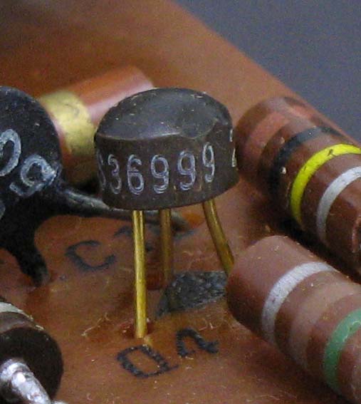
TRANSISTORS - There is a lot of hype about certain transistors that are more desirable in vintage Big Muffs than others. On the top of this list is the mysterious FS36999 transistor found in vintage V1 and V2 Big Muffs, which were actually 2N5133 transistors with a custom mark. Transistors have a gain measurement, called hFE. Technically it is a measurement of the forward current gain ratio in DC current transistors, not the "gain" people refer to when talking about the level of distortion produced by the pedal using the distortion/sustain knob. The F stands for forward and E means the transistor connection is in emitter mode. One transistor type may have higher or lower hFE than another, and those values can vary greatly among the transistors of the same type. The specs for original 2N5133 transistors were in the 60-1000 range. When I started collecting Big Muffs it was generally assumed that the best sounding vintage units had high hFE transistors in the 400-600 range. When I pulled all four FS36999 transistors from an exceptional sounding 1973 Big Muff in my collection and measured the hFE I found it ranged from 164 to 204. I also pulled the transistors from one of my Tall Font Green Russian Big Muffs and found they ranged from 200-250hFE. Here are some other hFE measurements of 2N5133/FS36999 transistors to give you an idea how much they varied.
1971 Triangle Big Muff - Q1: 702, Q2: 632, Q3: 655, Q4: 704
1972 Triangle Big Muff - Q1: 666, Q2: 286, Q3: 550, Q4: 233
1973 "47" Ram's Head Big Muff - Q1: 431, Q2: 473, Q3: 577, Q4: 425
1973 "Violet" Ram's Head Big Muff - Q1: 164, Q2: 204, Q3: 183, Q4: 161
1973 "Violet" Ram's Head Big Muff - Q1: 169, Q2: 189, Q3: 167, Q4: 193
1974 "White Can" Ram's Head Big Muff - Q1: 141, Q2: 168, Q3: 288, Q4: 152
Modern 2N5133 transistors are not exactly the same as the 1970s production. Some consider them almost too low for a Big Muff, although as stated, some 1970s 2N5133/FS36999 measure very low too. 2N5088 or 2N5089 are close modern production transistor equivalents. 2N5089 have a slightly higher gain than 2N5088. BC549C, BC550, BC239, SE4010, and 2N5210 are some others that also work.
Lower gain tranys are said to be smoother sounding than higher gain ones, and higher gain tranys are said to influence the mids and pick response, although actually hearing these differences is sometimes not an easy thing. Current gain of transistors should not be considered alone however, because the bias for the amount of gain for each clipping stage is set by the resistors coming from the collector and emitter of each transistor. The current gain does have an affect on certain aspects of the tone if it is very low or very high. Too too low and it may not have enough gain for the clipping sections to work properly and may be weak or dark sounding. There are other characteristics the transistors can affect as well as well, like clarity, raspiness, thickness, volume, and white noise level. Those characteristics can vary from transistor manufacturer to manufacturer, and vary between older and newer tranys of the same type. In a blind test, I could not pick out one over another listening to recorded samples, and differences I thought I heard changing them out using sockets were probably just my imagination. The only real difference I noticed was the transistor in the last stage. Different transistors and different hFE values seemed to alter the sound in that position, but it's a subtle difference.
I believe the effect different transistors have is minimal, but many pedal builders believe they have a large impact on the sound. That is why many of these makers screen batches of transistors to weed out the less desirable ones. Electro-Harmonix never screened transistors when they made the original Big Muffs. That may account for some of the wide variety of different sounding Big Muffs of the same model, but that variety really comes from the various different schematics used from one production run to the next, and how the component part values changed over time as the parts aged. I suggest not getting too hung up on the transistor type when looking for a vintage Big Muff though. A Muff with old 2N5088 or BC239 tranys may sound just as good, or bad, as one with old 2N5133 transistors. The other circuit components are much more important to the tone.
If you have never opened your vintage Big Muff up to look at the transistors on the PCB, here are INSTRUCTIONS for taking one apart.
 ..
.. ..
.. ..
..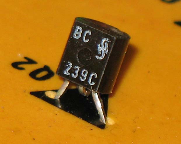
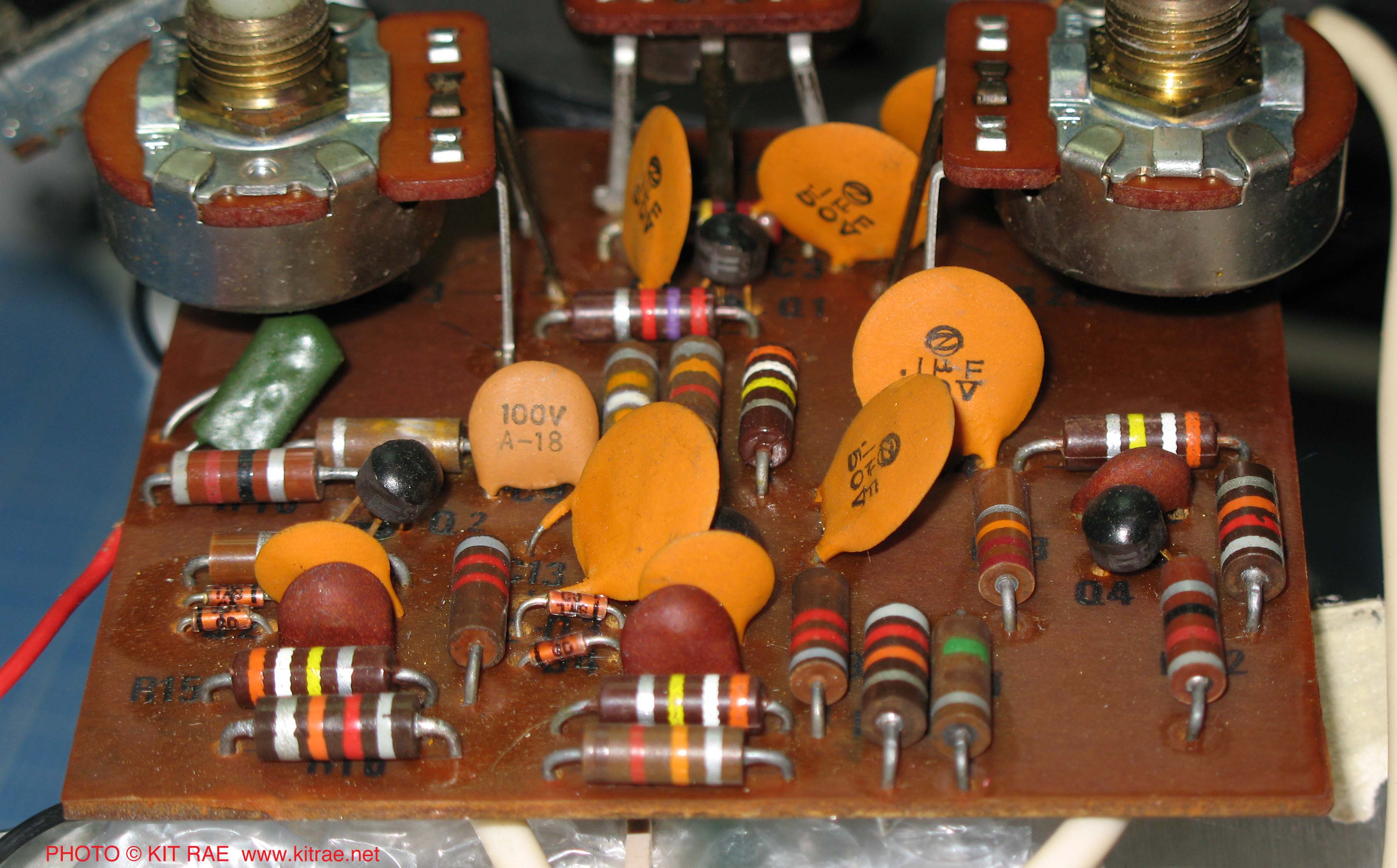
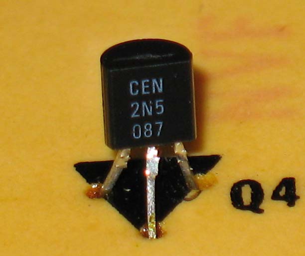
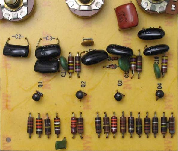
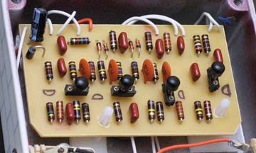
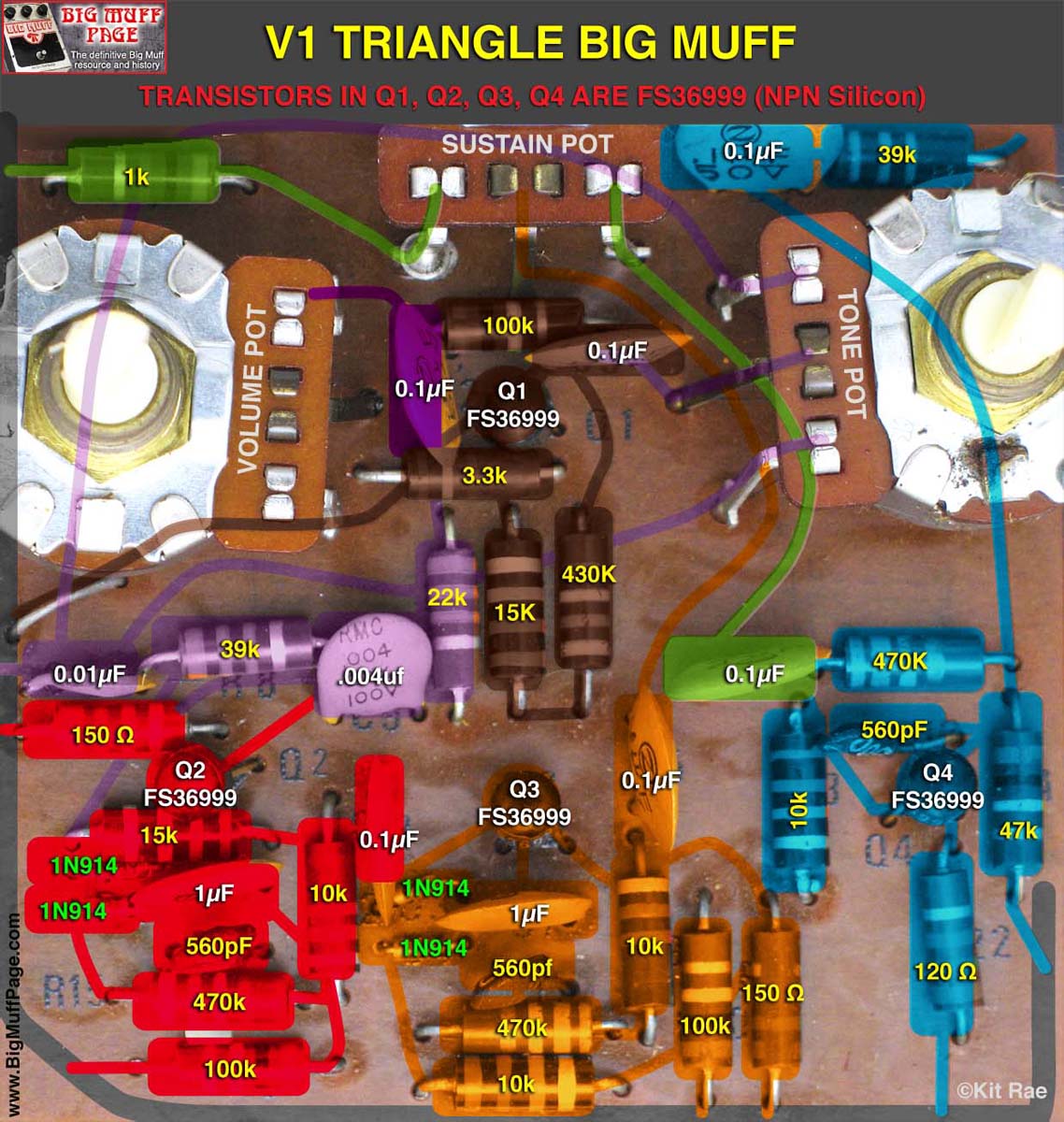
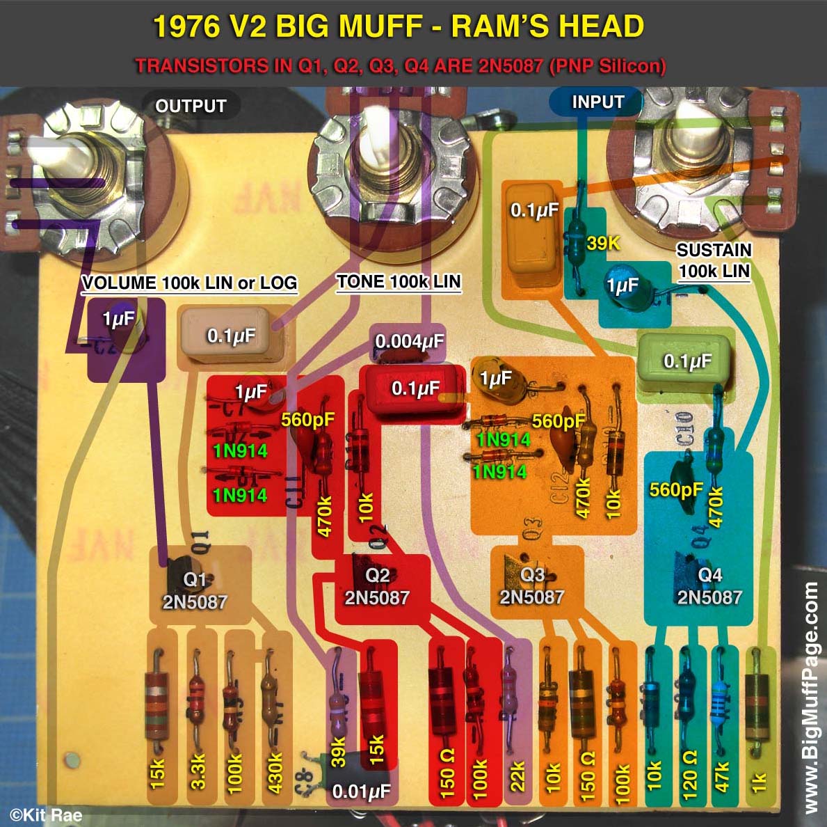
Shown on left: A vinatge V1 Big Muff circuit with ceramic capacitors, carbon composition resistors, and NPN FS36999 Silicon transistors. Shown on right are two other vintage Silicon transistors used in Big Muffs, the PNP 2N5087 and NPN BC239
CLIPPING DIODES - There were many different types of Silicon clipping diodes used. Although the effect is minor, different diode types do clip the sound frequencies in the clipping stages differently. Most modern Big Muffs and clones are made with general use 1N4148 or 1N914 diodes, which measure similar values to some of the diodes found in vintage Big Muffs, but not all. This is probably an overlooked aspect of the sound when creating clones of vintage circuits, but the problem is that many of those old diodes had non standard markings making it difficult to identify the actual type used, and many that were marked are no longer made. The forward voltage of the diodes used in Triangle and early Ram's Head Big Muffs varies from approximately 0.5 - 0.6.V. The diodes in an old perf board Triangle I own measure 0.481 - 0.487V, and diodes in a 1971 Big Muff measured 0.560 - 0.572. The diodes in a 1973 Ram's head Big Muff measured 0.586 - 0.626. Diodes from a Bubble Font Russian Big Muff measured 0.571- 0.580.
The diodes used in the V1 had various markings such as SYL GD938, or SYL GY925 926, SYL, GY920, or GY819. Most of the diodes used in the V2 were unmarked (black cathode band only). A few were marked 125 (1N125 is a germanium diode, but these were Silicon), and some from the 1975-76 period had 1N925 or 1N802 (gray/black/red bands) diodes. Diodes used in the V3 and V6 were 1N4148 or 1N914, and other were unmarked. Diodes used in the Russian made Sovtek Big Muffs were very different from the USA models, all of which are out of production. In general, they seem to clip more high frequencies than standard 1N4148 diodes. The Red Army Overdrive and Civil War Big Muffs used Russian KD521A and KD521V types. The Green Civil war and Tall Fonts and some Bubble Fonts used KD521A, KD521V, and 2D510A. Later Bubble Fonts and practically all Black Russian Big Muffs used KD522B.
RESISTORS - Electro-Harmonix used cheap carbon resistors throughout the 1970's (the fat dark brown cylinders with color bands), gradually switching to carbon composition type (smaller cylinders with fatter ends, and various case colors - tan, light brown, dark brown, red-brown) in the late 1970's and early 1980's. When the Big Muff returned to production in 2000 carbon composition was again used, with occasional use of some modern carbon film or metal film resistors (similar to carbon composition, but case color is usually blue) appearing in later years. What is the difference? Carbon and carbon composition resistor tolerances (electrical variance from part spec to actual measurement) are very high and film resistor tolerances are lower and more consistent from part to part. Some also claim film resistors are lower noise in audio circuits than carbon types. Having owned many Big Muffs with both types, and a few clones of the exact same circuit with all of one type, and all of the other type, I hear absolutely no difference in the level of noise between the two.
CAPACITORS - Electro-Harmonix used ceramic, poly film, polarized electrolytic, and various other capacitor types in all periods and models of Big Muff production. Some Big Muffs used all cereamic capacitors, some mixed film and ceramic, some mixed all types. It makes little difference in this circuit. Do they sound different? As with most audio electronics, opinions vary wildy. The general consensus among audio buffs is that film caps sound better in audio circuits than ceramic, but there is no evidence and the difference cannot be heard in blind comparisons. In fact, the evidence indicates the audible distortion differences are actually very well below what the human ear can hear or differentiate. My opinion is that if you can't hear it, it does not matter. All capacitors lose capacitance over time as the parts age, but leakage in electrolytics is faster than the other types, and tolerances (electrical variance from part to part) not very good. Film capacitors last much longer and have better tolerances than ceramic and electrolytic. However, in small signal circuits like effect pedals, the minor capacitance changes over time usually make little difference to the sound. If you add up the electical value changes across all parts in the whole circuit however, you would probably hear some difference between when the pedal was brand new versus thirty to forty years later.
VINTAGE COMPONENT MOJO - Some Big Muff enthusiasts argue that a particular set of component values (1uF clipping caps vs. 0.1uF caps, for example) give a Big Muff the best sound, but that is subjective based on the sound one person prefers that another may not. Some also think there is mojo in the old vintage components that make those Muffs sound much better than more recent issues (old ceramic caps vs new film caps, or old 2N5133 tranys vs newer 2N5088 tranys, for example), and I would tend to agree with that, as most of the Big Muffs I like best are the older ones. However, I have played vintage pedals side by side with exact clones made using modern components and the sound is very close. I'm not saying the mojo is not there in the older Muffs. It can be, and is in my opinion, but you can get one vintage Big Muff that sounds great and another that sounds average, with the exact same components. If you want a decent vintage Big Muff tone you don't necessarily need to fork over hundreds of dollars to buy a vintage one, hoping you get a good sounding unit, when you can spend under two hundred dollars and get a vintage Big Muff clone like the BYOC Large Beaver, or a Stomp Under Foot, all made with modern parts that are more consistant than most vintage parts.
 ...........................
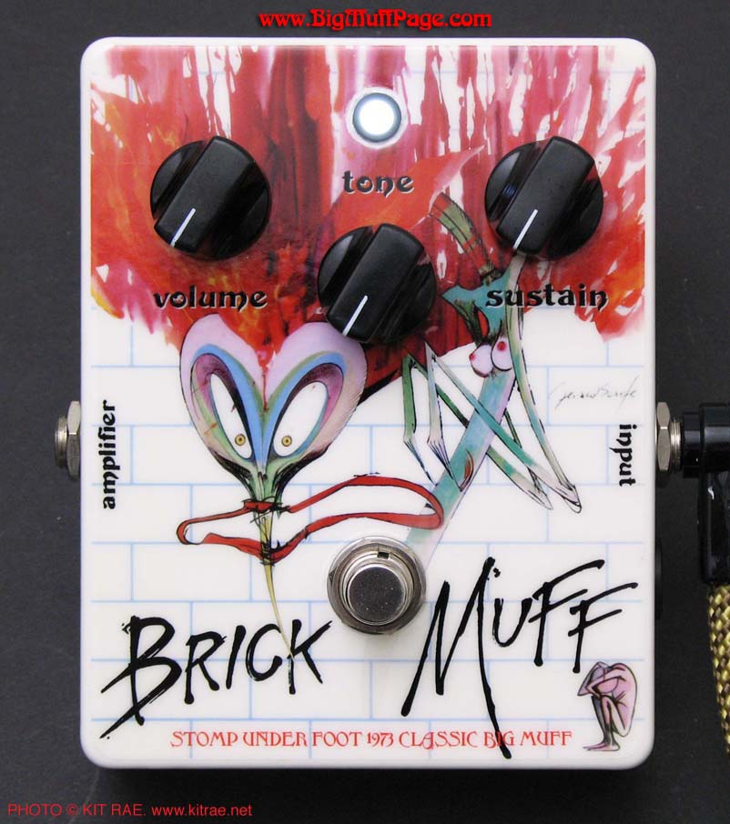
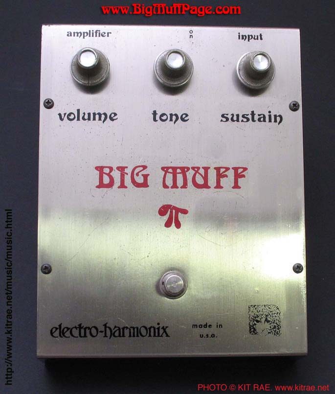
Shown above (left to right): A vintage 1973 Big Muff and the Brick Muff replica made by Stomp Under Foot for the Big Muff Classic series, using all modern components. The Brick was Big Muff Classic #4. The custom graphics were added by me using Gerald Scarfe's wonderful artwork created for Pink Floyd's The Wall.
THE '73 BIG MUFF VERSUS THE '73 S.U.F. CLONE TEST - Here is an experiment I did with one of my favorite vintage Big Muffs, a V2 "Ram's Head" Big Muff with 1973 pot dates (shown above), FS36999 transistors, polyester film caps, and all carbon comp resistors. Matt at Stomp Under Foot made an exact clone of this in 2010, the "Brick Muff", for his Big Muff Classic Series. It was based on my circuit trace of the original. The clone was made using modern carbon comp resistors, diodes, ceramic caps, and 2N5088 transistors. Matt is well known in the Big Muff community for making very accurate, high quality clones of just about every model or popular schematic of the various vintage Big Muffs, many of the-spin off vintage Big Muff variants, and his own unique Big Muff type pedals. Here are sound clips comparing the original '73 BM to the Brick Muff, with the volume, tone, and sustain matched as close as possible. In each clip, the '73 Big Muff is first and the Brick is second. Played with a Fender Strat loaded with a Seymour Duncan SSL-5 bridge pickup and Fender CS '69 neck pickup into a Reeves Custom 50 (Hiwatt Custom 50 replica) with Vintage Purple "Fane" replica speakers.
Comparison with Chords and Rhythm
Comparison of solos 2 - David Gilmour style solos with Compulator, CE-2, Carbon Copy
Do they sound the same to you? They are different, but the differences are minor. There is a bit more fuzz in the bass notes with the SUF pedal, and a slightly different feel to the clarity of the fuzz. The original is slightly tighter in the bass. The differences are more noticable when using modulation, as these filters can bring up frequencies that are not as noticable without. There is also a slightly different feel between the two when playing. However, overall I feel these two pedals sound and play 90% the same. Is that extra 10% the vintage mojo? Perhaps. The slight difference in transistor and diode types could be a factor. We have no idea what type the original diodes were as they are unmarked. It could also be that the component values in the vintage Big Muff have slightly changed over time as the materials decayed, giving some parts a slightly different tolerance than what they are labeled. Capacitors lose capacitance with age. Those values marked on the vintage components may be unreliable as well, so the actual values of the older parts versus theb newer may account for the slight difference. I suspect that if each component value were individually removed from the circuit, measured, and exactly matched (they were not), these two pedals would sound even closer. But still, the similarity is incredibly close considering these two pedals were crafted with components made around 37 years apart!
Not long after this demo, I replaced the 5088 transistors in the SUF clone with a set of high hFE Fairchild SE4010 transistors. These seemed to get the clarity slightly closer to matching the original FS36999 transistors in the 1973 Big Muff (though most 4010 tranys are actually very low hFE), but in a blind test I could not tell which was which. I was also able to test a set of supposedly vintage 2N5133 (thanks to Darrin) transistors with hFEs in the 800s against the modern SE4010s and 2N5088 transistors. Based on my experience with these in vintage Big Muffs, I thought for sure that the 2N5133 tranys would make a much more noticable difference. Surprisingly, there was not much difference, if any. Later, I pulled all four FS36999 transistors from a 1973 Big Muff that I had apart for repair and measured the hFE. Two measured in mid 160s, one 184, and one 204. Hardly what I would call a hight current gain.
I think the majority of the tone signature is really determined by the key cap and resistor values, NOT by the transitor type. To a lesser extent, the diode types can also make a difference in the tone because they affect the frequncies clipped in the clipping stages. Poor quality transistors can also affect how noisy the pedal will be.
VINTAGE VS. NEW - Modern Electro-Harmonix Big Muff pedals and custom "boutique" versions of the Big Muff circuit like the Blackout Effectors Musket or Skreddy Pig Mine are all made with modern components. They sound very different from eachother, and very different from vintage E-H Big Muffs. What sounds "good" all depends on the individual - what tone you are looking for or what tone you prefer, as well as the guitar ans amp used. Some people dislike the current E-H Big Muffs, citing that the old ones simply sound far superior. They do sound different, but that is because E-H is always changing the circuit with each new version so it WILL sound different. This is sort of a tradition with each new Big Muff model made. Does that mean the new Muffs sound inferior? Again it is all a matter of preference. The "older is better" thought does not hold up when you look at reliability of old components versus new, but many prefer the older tones simply because they are not common with modern Big Muffs. I also suspect there is occasionally some feeling of superiority from someone who paid $500-$1000 for a vintage Big Muff which causes that person to talk negatively about the newer Muffs, which typically sell for under $100. Regardless, which one a person likes is really just a matter of individual taste. David Gilmour of Pink Floyd made his vintage Ram's Head Big Muffs, as well as his modern Pete Cornish made Big Muff clones and variants, sound incredibly fluid and melodic, and unlike any other guitarist. In a totally different style of music, someone like Jack White of the White Stripes makes fantastic, raw, and raunchy distorted guitar tones, simply using a modern USA reissue Big Muff. I think both eras sound different, but equally great.
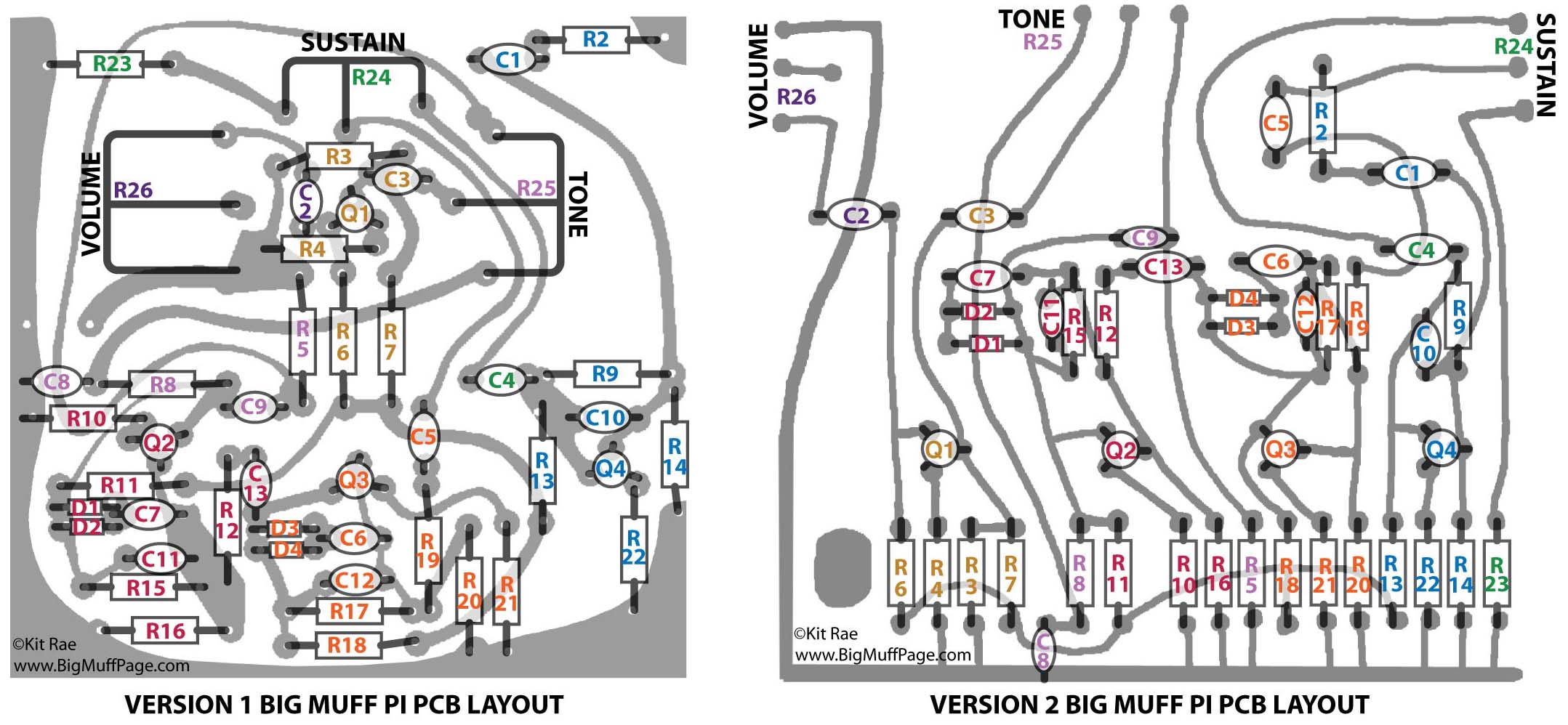
VERSION 1 AND VERSION 2/3 BIG MUFF LAYOUT FOR PARTS AND CIRCUIT STAGES - Below are pictures of typical V1 and V2 circuits with stages broken down by color. Below that are the part numbers on the PCB layout drawing, which correspond to the part numbers on the Circuit Guide, and all schematics on this website (R stands for resistor, C for capacitor, and Q for transistor). The V2 circuit layout also applies to the V3 Big Muff. Note that the V1 and V2 circuit boards both follow an identical circuit pathway, only the layout shape is different. Also note that the component values for the V1 and V2 Big Muff circuit boards shown below are identical to the Circuit Guide schematic (shown above) for easy identification of the part locations in the circuit, but real vintage Big Muffs rarely have identical component values.
WHY ARE THE TRANSISTORS LABELED IN THE REVERSE ORDER? - Note that Q1-Q4 are labeled in reverse order from input to output on the schematics. This is due to the fact that both V1, V2, and V3 Big Muffs have them printed in this order on the PCB's. To keep it from being confusing for those reading thier PCB's, and to keep the tradition, we have used this order on all Big Muff schematics.
The particular circuits shown below are negative ground, and positive ground, as real vintage BMPs were made with both PNP and NPN transistors. There is no real affect on the sound either way.
 ...
...
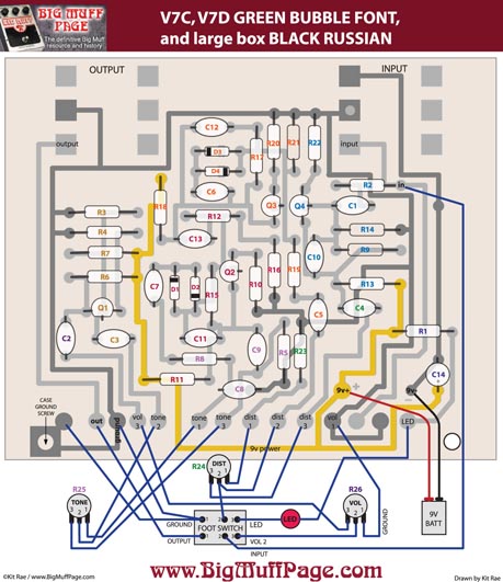
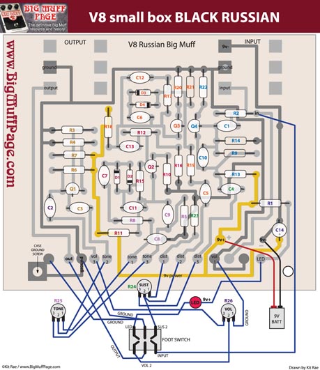
V7C, V7D, and V8 SOVTEK RUSSIAN BIG MUFF LAYOUT FOR PARTS AND CIRCUIT STAGES - Below are circuit layouts for the original Tall Font Green Russian (V7C), Bubble Font Green Russian/large Black Russian(V7D), and small Black Russian (V8) Big Muffs. The actual pcb's for the Bubble Font and V8 versions are slightly different from each other, but the trace pattern and parts location is identical for each. Part numbers correspond to the part numbers on the Circuit Guide, and all schematics on this website. Note that various foot switches were used, so the switch lug pins in some Sovtek Big Muffs may not correspond to what is shown here.
Here are INSTRUCTIONS for disassembling a vintage Big Muff.
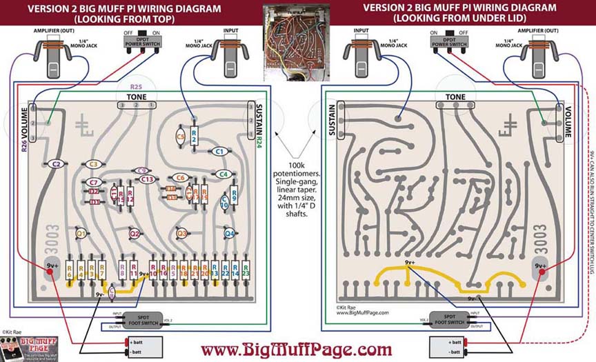
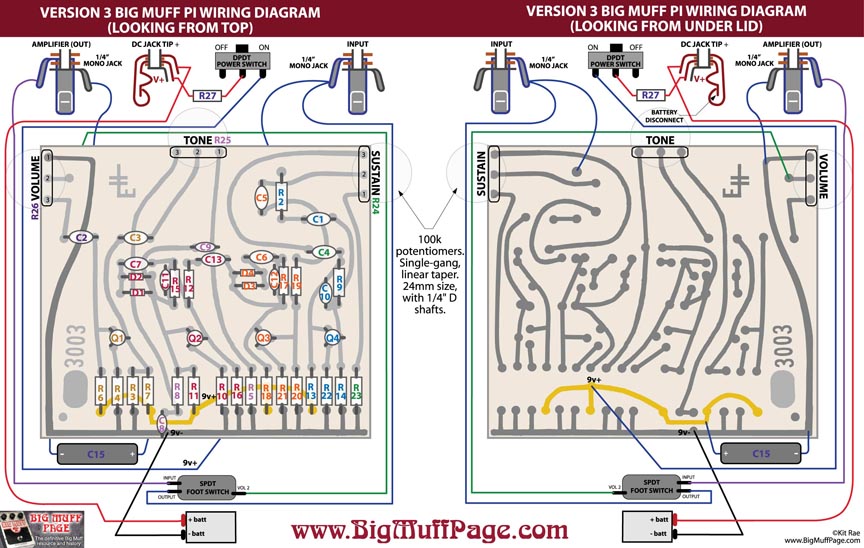
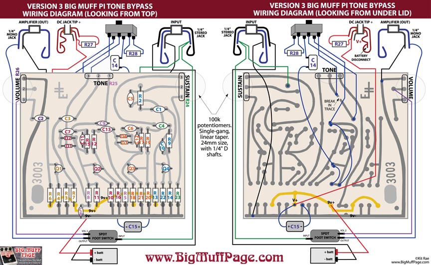
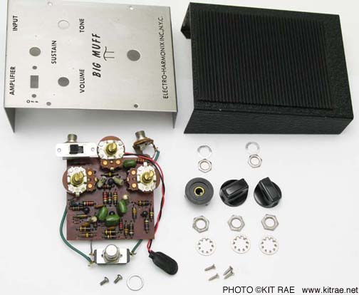
REPLACEMENT POTS - Vintage USA Big Muffs (V1, V2, V3) have single-gang, linear taper, 24mm,100k potentiomers. Electro-Harmonix used pots from various makers, but they were usually the 24mm size, with 1/4" D shaped knob shafts. 250k linear can be substituted for the volume and sustain pots if 100k are not available. 100k Logarithmic taper pots, or "audio" pots, will also work, but they are more expensive than linear, and the useful volume range gets squeezed into a smaller area of the knob rotation. The difference between linear and logarithmic/audio pot types is that linear increases (electrical resistance) evenly as you turn the knob, whereas log has a shorter increase at both ends of the knob rotation, but a longer, increase in the middle. That that wider spectrum in the middle means a more usable range to allow better fine tuning with a log pot, in a tone knob for example, but not the best for a Big Muff volume pot. Both types sound the same, but the knobs will be in different positions for the same volume, tone, or gain level. A
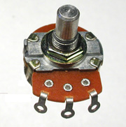
Something to keep in mind, some pots are letter coded with A or B to represent linear or logarithmic, but there is no worldwide standard for which is which. In general, the USA standard, which I believe came from Japan, is A=log/audio and B= linear. The European standard is A=linear and B=log/audio. For example, a USA made pot may be marked B100k, which means 100k linear taper. A100k would mean 100k logarithmic/audio taper.
V4 and V5 op-amp Big Muffs were made with 10k linear taper Sustain and Tone pots (marked PO130 or ZA2124). The Volume pot was 100k linear (marked XM2184 or PO150), but some early V4's had 50k volume pots and some late model V5s had 150k.
V6 Big Muffs tended to have all 150k linear taper pots.
V9 Big Muffs had varied pots, with some using all 100k linear pots, and some using 500k logarithmic volume pots.
Russian made Big Muffs have Russian made pots, usually 100k linear taper, but often the volume pot was logarithmic. You can use 100k audio log taper for the volume and sustain pots. EHX also used 150k pots at times. Replacements could be found at Small Bear Electronics at the time this article was written.
If you replace an old pot with a new one of the same size, it is sometimes hard to find pots with the same pot shafts that fit the old knobs. You can pull the shafts out of the old pots and install them in the new ones. For vintage USA Big Muffs, carefully bend back the four tabs on the top/back of the casing on the old pot, slide the casing off, then remove then shaft. Open the new pot this same way and install the old shaft. Be very careful not to damage the internal tracks.
Small Bear Electronics carried Big Muff replacement pots at the time this article was written, but many other electronics suppliers carry them as well.
REPLACEMENT TRANSISTORS - Many of the original transistors types used in vintage Big Muffs are no longer made. 2N5088 or 2N5089 Silicon transistors are the closest modern production equivalents to the FS36999/2N5133 transistors used the the early 1970s Big Muffs. 2N5089 have a slightly higher gain than 2N5088. BC549C, BC550, BC239, SE4010, and 2N5210 are some others that also work in the circuit. 2N5089 or 2N5210 are near eqivalents to the transistors used in early Russian made Big Muffs as well.
REPLACEMENT ENCLOSURE SCREWS - The screws used for vintage and modern large sheet metal enclosures for the USA made Big Muffs can be replaced with #4 pan head phillips screws, 3/8" or 1/2" length. These can be found found at most large hardware stores or online. Fender pan head pickguard screws are the same size. If the screw holes are stripped out, larger #6 sized screws oftern work.
For older Russian Big Muffs, use metric sized screws. The original innner enclosure lid scrws for large box Russian Big Muffs were Sovtek 1590NS, 1790NS. The outer box screws were Sovtek 1290NS. Both could be found at Small Bear Electronics at the time this article was written.
REPLACEMENT KNOBS - There were dozens of different knob types used on V1 and V2 vintage USA Big Muffs. Unfortunately, most of these are no longer in production. I have not had any luck finding anything similar in current production, so I resorted to taking Silicon rubber molds of some of my knobs and casting resin copies as replacement for missing knobs in my collection.
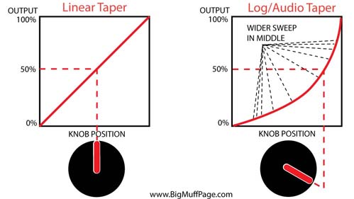
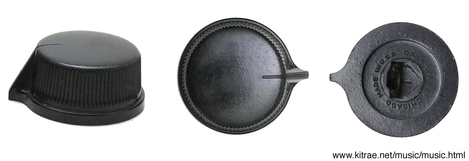
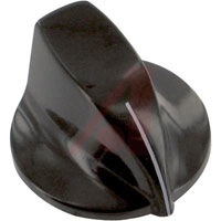
Shown above: For replacements of the original black bakelite V1 Big Muff "pinch" style knobs, you can occasionally find the exact same originals by searching Ebay for "vintage radio knobs." These same knobs were used on RCA Victor and Phillips radios in the 1940's and 1950's. For something similar, try modern Davies Molding #1550 knobs. Not exactly the same shape, but approximately the same size. I have also seen some modern accurate replica knobs being sold on ebay from time to time. Note that most vintage Big Muffs had D shaped posts, so D shaped post holes or knobs with round holes and a set screw are necessary. Remove your knobs to see which type you have.
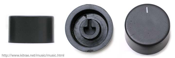
Shown above: V2/3/4/5 Muffs all used Daka Ware style pointer knobs with D shafts. They are still being made by Davies Molding at the time I write this (2011) and can be found online, Davies model #1470. There is a D shaft version (Small Bear #0803M) and an identical version with a set screw in the side (Small Bear #0803), so it works on D or round shafts. OEM replacements for those can be found at Small Bear Electronics. Pedal Parts Plus also carries replacement knobs that can be used. Note that most vintage Big Muffs had D shaped posts, so D shaped post holes or knobs with round holes and a set screw are necessary. Remove your knobs to see which type you have.
Shown above: Hockey puck shaped knobs used on V5/V6 and modern V9 Big Muffs (Small Bear #0832) and the smaller hockey puck style knobs used on the Little Big Muff (Small Bear #0830) are made by Electro-Harmonix. OEM replacements for those can be found at Small Bear Electronics. Pedal Parts Plus also carries replacement knobs that can be used. Note that most vintage Big Muffs had D shaped posts, so D shaped post holes or knobs with round holes and a set screw are necessary. Remove your knobs to see which type you have.

.jpg)
Shown above: Davies model #1470, #1550, and the modern EHX "hockey puck" knobs.
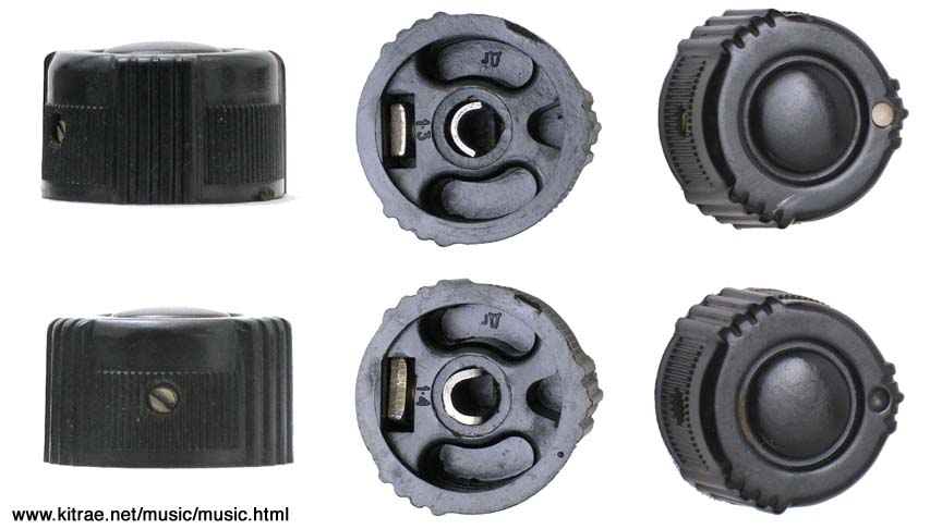
Shown above: Old Russian dimple-top knobs
These are not manufactured anymore, but they occasionally show up on ebay. You can also occasionally find similar vintage art deco knobs from the 1940's and 1950's by searching Ebay for "vintage radio knobs". The black plastic pointer knobs used on some of the last small box Russian Big Muffs are still made by Davies Molding and can be found online practically anywhere that sells knobs for pedals. Small Bear Electronics and Pedal Parts Plus carry a range of replacement knobs that can be used.
RUSSIAN BIG MUFF BATTERY DOORS - Small Bear Electronics was selling the metal battery doors online for a time. They fit the green Bubble Font Big Muffs. There are no plastic replacement doors available for the earlier Russian made Big Muffs. As a substitute for the plastic doors, I have used a piece of aluminum or steel sheet metal, folded and cut to size with wire cutters.
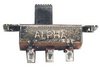
REPLACEMENT SLIDE SWITCHES - Power and tone bypass switches on vintage USA Big Muffs are Alpha Slide DPDT 90 size. Small Bear Electronics carries Big Muff replacement switches.
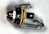
REPLACEMENT JACKS - In general, the input jack is stereo and the output jack is mono. 1/4" size Switchcraft or Neutrik jacks can be used as replacements for USA Big Muffs. Switchcraft #11 or Neutrik #NYS229 can be used for the mono jack, and Switchcraft #12B or Neutrik #NYS230 can be used for the stereo jack. Small Bear Electronics and Pedal Parts Plus carreied these jacks at the time this article was written.
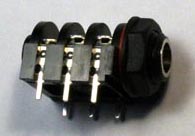
Russian Big Muff jacks were the enclosed type, with leads soldered directly the the pcb. This style jack and plastic jack nuts could be found at Small Bear Electronics at the time this article was written. Any 1/4" open jack can be used for a Russian Big Muff, but those type require wires to run the leads to the circuit board.
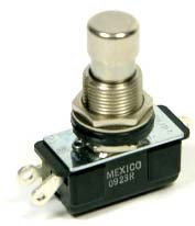
REPLACEMENT FOOT SWITCHES - Vintage USA Big Muffs use old Carling SPDT (Single Pole Double Through) three lug foot switches. These are sometimes hard to find. The modern Carling model is #112-P, or you can get a Dunlop version, #ECB-69, often used for Crybaby Wah pedals. When replacing a foot switch in a modern Big Muff , use a modern 3PDT foot switch as those are wired for true bypass.
The large Russian made foot switches used on the older, large box Russian Big Muffs are no longer available. Originals were a type of DPDT (double pole, double throw), but these were not wired the way a standard DPDT is wired, so it is not as simple as just de soldering each wire and re soldering to the same lug on the new switch. I have also seen some originals that had SPDT (Single Pole Double Throw) foot switches inside. Most people will find it easier to wire for true bypass using a 3PDT switch rather than try and replace the orignal. Since the enclosure hole is so much larger than a typical pedal, you must attach a small metal plate that is slightly larger than the switch hole, over the existing hole. Drill a smaller hole in it to accommodate the small switch. Small Bear Electronics and Pedal Parts Plus carry DPDT and 3PDT switches.
 ...........
ENTER THE SITE FOR A HISTORY OF ALL BIG MUFF VERSIONS
Kit’s Secret Guitar, Gear, and Music Page
Guitar stuff, gear stuff, soundclips, videos, Gilmour/Pink Floyd stuff, photos and other goodies.
Copyright Kit Rae.
VISIT MY SWORDS, KNIVES and FANTASY ART WEBSITE www.kitrae.net


This page is not authorized, affiliated, or associated with Electro Harmonix in any way.
Website and contents ©2007 and ©2010 Kit Rae. All rights reserved. Linking to this website is allowed, but copying the text content is strictly prohibited without prior authorization. No part of this work may be reproduced, stored in a retrieval system, or transmitted in any other form, or by any means, electronic, mechanical, photocopying, recording, computer networking, or otherwise without prior permission in writing from the copyright holder(s).